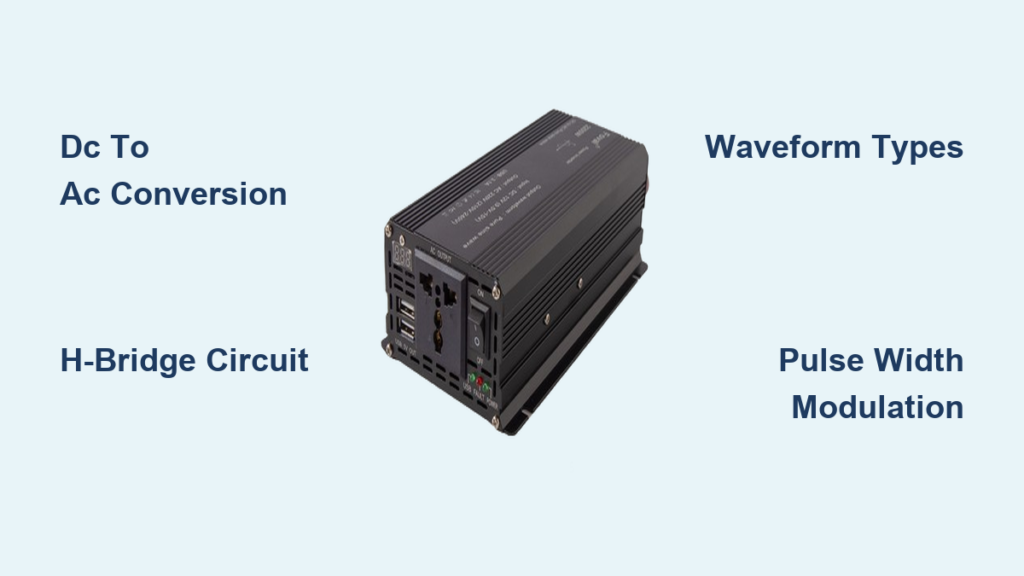
A power inverter transforms direct current from batteries, solar panels, or vehicle systems into alternating current that runs household appliances and electronics. This conversion makes off-grid living, solar energy systems, and portable power possible. Without an inverter, the DC electricity stored in your car battery or solar panels would be useless for powering standard devices that require AC. This guide explains the technical process behind DC to AC conversion, the internal components that make it work, waveform differences, and how to choose the right inverter for your needs.
DC to AC Conversion: The Core Function
A power inverter reshapes existing electricity rather than generating new power. Its primary role is converting direct current into alternating current because most appliances run on AC power while renewable energy sources and batteries produce DC. This conversion bridges the gap between portable power sources and fixed electrical infrastructure.
AC dominates household and industrial power grids because it can travel long distances efficiently and voltage can be stepped up or down easily using transformers. High-voltage transmission minimizes energy loss across power lines before reducing to safe 120V or 230V for home use. Inverters replicate this process by taking low-voltage DC and producing usable AC that matches grid standards.
The inverter output capacity depends on both the DC source strength and the inverter efficiency rating. A weak battery or undersized inverter will deliver poor performance or shut down completely when confronted with demanding loads like air conditioners or power tools.
Why AC Powers Your Home
AC became the global electrical standard because it solves fundamental transmission problems. Power plants generate electricity hundreds of miles from homes, and DC loses significant energy as heat during long-distance travel. ACAlternating current allows transformers to boost voltage for efficient transmission, then reduce it safely for household use. Most appliances are engineered around this AC infrastructure, from refrigerators to televisions.
Inverters Enable Modern Power Solutions
Inverters connect DC sources to AC loads across many applications. Solar power systems rely on inverters to convert panel output into home-compatible electricity. Uninterruptible power supplies use inverters to keep devices running during outages. Electric vehicles employ inverters to power AC motors from battery DC. Recreational vehicles and boats use inverters to run standard appliances from battery banks.
The H-Bridge: How Inversion Actually Works
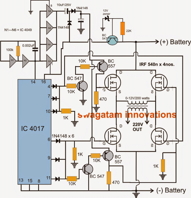
The H-bridge circuit forms the heart of every inverter, using four electronic switches arranged in an H shape around a load. This arrangement allows current direction reversal, which creates the alternating pattern that defines AC power.
Rapid Polarity Switching Creates AC
Two switch pairs alternate control of current direction. When the first pair activates, current flows in one direction producing the positive half-cycle. When the second pair activates, current flows the opposite direction producing the negative half-cycle. Repeating this switching 60 times per second generates 60 Hz AC standard in North America. Repeating 50 times per second produces 50 Hz AC used in Europe, Asia, and Africa.
This basic switching produces a square wave, the simplest form of AC. Square waves work for basic devices like incandescent bulbs and heaters but contain sharp voltage transitions that can damage sensitive electronics.
Modern Switching Components
Solid-state transistors replaced mechanical relays in contemporary inverters. IGBTs handle high-power applications like solar inverters and electric vehicles, managing high voltage and current while maintaining low conduction losses. MOSFETs serve lower-voltage designs requiring faster switching speeds, common in portable inverters. Both components enable compact, reliable, and efficient modern inverter designs.
Waveform Types and Power Quality
Inverter output waveforms vary significantly, affecting device compatibility and performance. Understanding these differences helps you select the right inverter for specific applications.
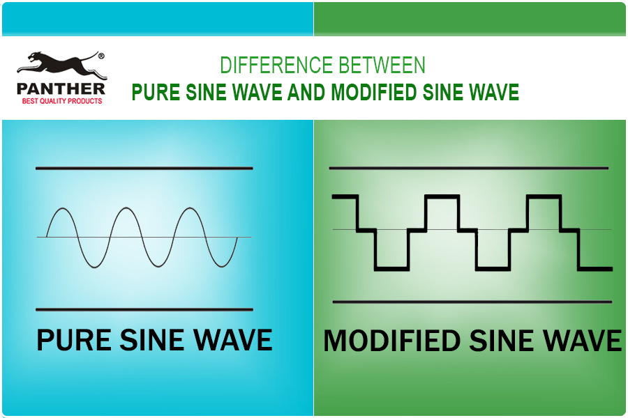
Square Wave Output
Square wave inverters switch abruptly between positive and negative voltage levels. This produces Total Harmonic Distortion around 45-48%, meaning the output contains significant harmonic content that deviates from clean AC. Square waves work adequately for simple resistive loads like heaters and basic lighting but can cause overheating in motors and malfunction in sensitive electronics. This type is rarely used today except in very low-cost or obsolete units.
Modified Sine Wave Performance
Modified sine wave inverters produce a stepped waveform pattern climbing from zero to positive peak, back through zero to negative peak, then returning to zero. This reduces THD to approximately 23-30%. These inverters work well with many modern switch-mode power supplies found in laptops and phone chargers, plus incandescent bulbs and basic tools.
However, modified sine waves may cause audible hum in audio equipment, overheating in transformers and motors, and reduced efficiency in inductive loads like refrigerators and power tools. These limitations make them unsuitable for sensitive electronics or precision equipment.
Pure Sine Wave Quality
Pure sine wave inverters replicate utility-grade power with THD below 3-5%. This clean output matches grid power quality and works with all AC devices. Pure sine wave units use Pulse Width Modulation and filtering to achieve smooth, continuous waveforms.
This waveform type is essential for inverter air conditioners, medical equipment, audio and video systems, laser printers, and battery chargers. Despite higher cost, pure sine wave inverters provide the best reliability and compatibility for sensitive devices.
Pulse Width Modulation Explained
Pulse Width Modulation shapes inverter output into clean sine waves by rapidly pulsing switches within each AC cycle. This technique varies pulse width to control average voltage delivered to the load.
How PWM Creates Sine Waves
Narrow pulses produce low average voltage near zero crossings of the sine wave. Wide pulses produce high average voltage at peak points. By adjusting pulse duration across the complete cycle, the inverter builds a stepped approximation of a sine wave. A low-pass LC filter then smooths these pulses into clean sinusoidal output.
High-Frequency Switching Benefits
Modern inverters switch at frequencies between 20-100 kHz, well beyond human hearing range. This high switching frequency allows easy filtering by inductors and capacitors while avoiding audible noise. The LC filter removes switching artifacts while passing the fundamental 50 or 60 Hz frequency, delivering smooth low-distortion AC suitable for sensitive devices.
Stepping Up Voltage: 12V to 120V
Most DC sources provide low voltage like 12V, 24V, or 48V, yet household appliances require 120V or 230V AC. Inverters use two primary methods to increase voltage during conversion.
DC-DC Boost Converter Method
The boost converter first increases DC input voltage. For example, 48V might become 340-400V DC. This high voltage is necessary because the peak of a 240V AC sine wave reaches approximately 340V (240V × √2). The boost stage uses high-frequency switching with inductors and capacitors to store and release energy efficiently. Once boosted, the high-voltage DC feeds into the H-bridge for AC generation. This transformerless approach dominates modern inverters due to high efficiency and compact size.
Low-Frequency Transformer Method
Some inverters convert low-voltage DC to low-voltage AC first, then use a heavy iron-core transformer to step up voltage to 120V or 230V. This approach provides galvanic isolation creating a safety barrier between input and output. Transformer-based designs tolerate surges better but weigh more, respond more slowly, and experience higher losses. These designs remain common in high-reliability applications like ferroresonant UPS systems.
Key Components Inside an Inverter
Modern inverters integrate multiple stages and components working together to deliver stable, clean AC power from DC sources.
Input Stage and DC Conditioning
The input stage supports common DC voltages like 12V, 24V, and 48V. Electrolytic capacitors reduce voltage ripple and transient spikes, providing stable DC input. Protection circuits include fuses and circuit breakers for overcurrent protection, diodes for reverse polarity protection, and undervoltage or overvoltage shutdown to prevent damage from source fluctuations.
Control System and Brain Functions
A microcontroller or Digital Signal Processor manages the entire conversion process. This control system generates precise PWM signals for switch timing, monitors voltage, current, temperature, and load conditions, adjusts output in real-time through feedback loops, and implements protection logic for overload and thermal shutdown. Advanced models include communication interfaces for remote monitoring and grid synchronization.
Output Filtering
LC filters remove high-frequency switching noise and harmonics from raw inverter output. The inductor-capacitor combination passes the 50 or 60 Hz fundamental frequency while attenuating switching frequencies and harmonic content. This filtering stage is crucial for achieving low THD in pure sine wave inverters.
Three-Phase Inverters for Industrial Use
.png)
Heavy-duty applications require three-phase inverters generating three synchronized AC waveforms, each offset by 120 degrees. This configuration delivers smoother power and higher efficiency than single-phase systems for industrial machinery.
Six-Switch Bridge Configuration
Three-phase inverters use six IGBTs arranged in a bridge configuration with two switches per phase. The switching sequence cycles through six states producing rotating magnetic fields. Each line-to-line voltage follows a six-step waveform refined with PWM techniques. This creates balanced three-phase AC ideal for industrial motors and large-scale systems.
Three-phase inverters power industrial motor drives, HVDC transmission converter stations, electric vehicle traction inverters, large solar farms with centralized inverters, and inverter air conditioners with variable-speed compressors. These systems reduce mechanical stress and improve energy efficiency in rotating equipment.
Efficiency and Power Loss
Inverter efficiency determines how much input DC power becomes usable AC output. Most modern units achieve 90-95% efficiency, meaning 5-10% dissipates as heat.
Sources of Power Loss
Switching losses occur when transistors turn on and off. Conduction losses result from resistance in wires, traces, and semiconductor junctions. Core losses come from hysteresis and eddy currents in transformers and inductors. Capacitor ESR causes internal heating. Higher-end models use advanced materials like silicon carbide MOSFETs and optimized topologies to exceed 95% efficiency.
Calculating Power Requirements
Running a 1000W load through a 90% efficient inverter requires 1111W input power. At 12V battery voltage, this demands 92.6A of battery current. As battery voltage drops during discharge, current draw increases to maintain output, highlighting the importance of proper cabling and fusing.
Battery Runtime and Sizing
Battery capacity determines how long an inverter can power loads. Proper sizing prevents over-discharge and ensures reliable operation.
Calculating Runtime
Use this formula: Runtime (hours) = Battery Capacity (Ah) × Voltage (V) × Efficiency ÷ Load (W). For example, a 100Ah 12V battery powering a 200W device through a 90% efficient inverter runs for (100 × 12 × 0.9) ÷ 200 = 5.4 hours.
Usable capacity depends on battery chemistry. Lead-acid batteries should limit depth of discharge to 50%. Lithium batteries safely handle 80-90% depth of discharge.
Battery Configuration Options
Series connections increase voltage while reducing current for the same power, lowering transmission losses. However, one failed battery breaks the entire circuit. Parallel connections increase amp-hour capacity extending runtime but risk reverse current flow if cells become imbalanced. Use diodes or intelligent monitoring to isolate weak cells.
Common Applications
Power inverters enable energy flexibility across diverse fields from renewable energy to transportation.
Solar Power Systems
Grid-tied inverters synchronize with utility frequency and phase. Micro-inverters attach to individual panels for maximum power point tracking. Hybrid inverters combine battery charging and AC output in one unit. Solar inverters must meet strict grid interconnection standards.
Uninterruptible Power Supplies
UPS systems provide seamless backup during outages using battery-powered inverters to maintain AC output. Ferroresonant designs offer superior voltage regulation and noise filtering. These systems protect servers, medical devices, and network infrastructure.
Electric Vehicles
Traction inverters convert battery DC to three-phase AC for motors. They enable regenerative braking by reversing power flow and control motor speed through variable frequency output. EV inverters are highly optimized for efficiency, size, and thermal management.
Motor Speed Control
Variable Frequency Drives use inverters to adjust AC motor speed in HVAC systems, industrial pumps, and fans. Inverter compressors in refrigeration improve efficiency by eliminating on/off cycling and providing precise cooling control.
Safety and Protection Features
Modern inverters include multiple safeguards protecting equipment, users, and batteries.
Built-In Safety Mechanisms
Thermal protection shuts down the inverter if internal temperature exceeds limits. Overload protection limits or cuts output during excessive load conditions. Low battery disconnect prevents deep discharge damage. Surge handling temporarily supports startup currents from motor starting. Anti-islanding protection critical for grid-tied systems shuts down during grid failure to prevent dangerous backfeeding.
User-Friendly Enhancements
USB charging ports, multiple AC outlets, LED status indicators, remote monitoring via apps, and silent operation with smart fan control add convenience without compromising reliability.
Historical Evolution and Modern Trends
Inverter technology evolved from bulky electromechanical systems to compact high-efficiency electronics.
From Motor-Generators to Solid-State
Early inverters used motor-generator sets where a DC motor spun an AC generator. Thyratrons and mercury-arc valves provided early solid-state designs. Silicon-Controlled Rectifiers enabled static inverters in the 1960s. IGBTs and MOSFETs took over due to superior control, speed, and reliability, enabling miniaturization and mass adoption.
Current Technology Trends
The 2014 Little Box Challenge pushed inverter size reduction. Transformerless designs now dominate solar and EV applications. Wide-bandgap semiconductors like silicon carbide and gallium nitride improve efficiency and switching speed. Smart inverters support grid services including voltage regulation and frequency support.
Frequently Asked Questions About Power Inverters
What is the main function of a power inverter?
A power inverter converts direct current from batteries, solar panels, or vehicle systems into alternating current that household appliances and electronics require to operate.
Can I run all appliances on a modified sine wave inverter?
No. Modified sine wave inverters may cause problems with sensitive electronics, medical equipment, variable-speed motors, and audio devices. These require pure sine wave output for proper operation and safety.
How efficient are power inverters?
Most modern inverters operate at 90-95% efficiency, meaning 5-10% of input power is lost as heat during conversion. Higher-end models using advanced semiconductors can exceed 95% efficiency.
What size inverter do I need for my battery system?
Calculate your total load wattage, then choose an inverter rated at least 20-30% higher than your maximum expected load. Ensure your battery capacity and voltage can supply sufficient current for your intended runtime.
Do inverters draw power when no load is connected?
Yes. Inverters consume a small amount of power even when idle, called phantom or vampire draw. This typically ranges from 0.5-5 watts depending on inverter design and quality.
Key Takeaways for Understanding Power Inverters
A power inverter works by converting DC to AC through high-speed electronic switches in an H-bridge configuration, controlled by PWM and filtered to produce clean power. The three main waveform types are square wave (basic but limited), modified sine wave (balanced performance), and pure sine wave (grid-quality output). Choosing the right inverter type depends on your load requirements, with pure sine wave being essential for sensitive electronics while modified sine wave suffices for basic devices. With proper sizing and protection features, inverters reliably deliver grid-quality power anywhere, enabling solar systems, backup power, electric vehicles, and off-grid living. Consider efficiency ratings, voltage requirements, and safety features when selecting an inverter for your specific application.