You plug in your phone, the screen lights up with a charging icon, and within hours it is back to 100%. But what is really happening behind that simple action? The question “how does a charger work” reveals a surprisingly complex process that blends physics, electronics, and intelligent design to deliver safe, efficient power. Far from just passing electricity through a cable, modern chargers convert, regulate, and communicate with your device to ensure optimal performance and safety.
At its core, a charger transforms high-voltage alternating current from your wall outlet into low-voltage direct current that your phone battery can store. But the real magic happens in the details: switching circuits, feedback loops, isolation barriers, and smart negotiation protocols all play critical roles. This is not just a power adapter, it is a precision power management system. In this guide, we will break down every stage of how a charger works, from the first spark of AC input to the final trickle of charge before your battery hits full.
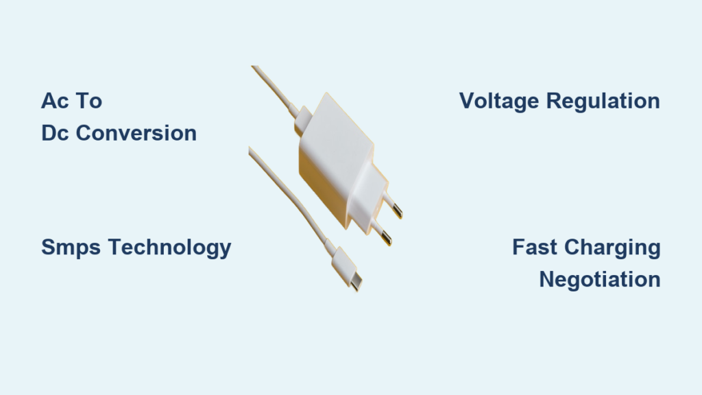
Why Chargers Must Convert AC to DC
Your home runs on alternating current, but your phone needs direct current. This fundamental mismatch means the charger must perform a critical transformation before any charging can occur. Batteries store energy chemically, and the reactions involved require a unidirectional flow of electrons, exactly what DC provides. Alternating current reverses direction 50 to 60 times per second and would prevent stable charging.
Wall outlets supply high voltage, typically 120V or 230V depending on your region. Most USB devices operate at 5V DC, which is less than 5% of the input voltage. Without proper step-down, connecting mains power directly would instantly destroy internal circuitry. The charger performs two essential tasks: converting AC to DC and stepping down voltage to safe levels.
SMPS Technology: Why Modern Chargers Are Small and Efficient
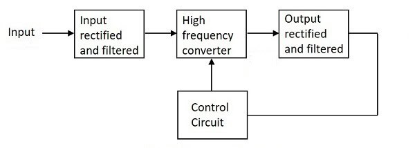
Older chargers used bulky linear transformers that dissipated excess energy as heat and achieved less than 50% efficiency. Today’s sleek, efficient models rely on Switch-Mode Power Supply technology, which enables miniaturization, high efficiency, and thermal stability. SMPS units operate at much higher frequencies, typically 15 to 50 kHz, allowing smaller components and achieving 80 to 90% efficiency.
The key advantages of SMPS design include significant size reduction, often up to 80% smaller than linear equivalents. These units generate less heat because minimal energy is wasted. They are also much lighter, making them ideal for portable devices. At higher frequencies, magnetic fields change rapidly, meaning transformers can use smaller cores to achieve the same power transfer. This shift from low-frequency to high-frequency operation is why today’s 65W GaN chargers are smaller than old 5W linear bricks.
Step-by-Step: Inside a Charger Circuit
Every charger follows a sequence of stages to convert and regulate power. Here is how it happens, one step at a time.
AC Input and Initial Protection
The process begins when the charger plugs into a 120V or 230V AC outlet. A fusible resistor limits inrush current during startup and acts as a safety fuse. If overloaded, it breaks the circuit and protects downstream components. You might hear a soft click when plugging in, which is the initial surge being controlled.
Rectification: Converting AC to Pulsating DC
A bridge rectifier, typically made of four diodes, converts AC into pulsating DC. Diodes allow current to flow in only one direction, flipping the negative half of the AC wave to positive. The output is approximately 300V pulsating DC from a 220V RMS AC peak.
Primary Filtering
A high-voltage capacitor smooths the pulsating DC into a more stable high-voltage DC rail. This prepares the signal for high-frequency switching. Even when unplugged, this capacitor can hold a dangerous charge, so never open a charger unless trained.
High-Frequency Oscillation
Transistors switch the DC on and off rapidly, creating high-frequency AC in the 15 to 50 kHz range. This forms the heart of the SMPS oscillator. Feedback from an auxiliary winding sustains the oscillation, and this high-frequency AC is now ready for transformation.
Voltage Step-Down and Isolation
A high-frequency transformer reduces the voltage from approximately 300V to 5V while providing galvanic isolation. This is a crucial safety barrier between lethal mains voltage and the safe output. The primary winding receives high-voltage AC, the secondary winding outputs low-voltage AC, and the auxiliary winding powers the oscillator and feedback loop. Isolation prevents electric shock even if someone touches the USB port.
Secondary Rectification
The stepped-down AC from the secondary coil is converted back to DC using a Schottky diode. Unlike standard diodes, Schottky types have a lower forward voltage drop, faster switching speed, and higher efficiency at high frequencies. This improves overall charger efficiency by reducing heat loss.
Output Filtering
An electrolytic capacitor smooths the pulsating DC into a clean, stable 5V output. This final filtering ensures the voltage delivered to your device is ripple-free and consistent. Poor filtering causes erratic charging and device instability, which is why cheap chargers often cut corners here.
Feedback Regulation via Optocoupler
The most critical safety and regulation component is the optocoupler. It enables closed-loop control without electrical connection between the primary and secondary sides. The output voltage is monitored by a Zener diode. If voltage exceeds 5V, the Zener conducts and lights the optocoupler internal LED. This light activates a phototransistor on the primary side, which reduces oscillator activity and lowers output voltage. This light-based feedback loop keeps output precisely regulated under load and input variations.
Where Charging Actually Happens
Despite common belief, the wall charger does not charge the battery. It only supplies power. The actual charging process occurs inside the device, managed by the Battery Management System. The BMS monitors battery voltage, current, and temperature. It implements CCCV charging, which stands for Constant Current followed by Constant Voltage. The BMS prevents overcharging, overheating, and deep discharge. It also communicates with the charger via protocols like USB-PD.
A 65W charger delivers power, but the phone BMS decides whether to accept 5V/3A, 9V/3A, or 20V/3.25A. The charger and device negotiate the optimal power level together.
Fast Charging: How Speed Is Achieved
Fast charging is not just about higher wattage. It is about smart negotiation between charger and device. The power equation is simple: Watts equal Volts times Amps. Increasing either voltage or current increases power. A standard charge is 5V times 1A, which equals 5W. Fast charging might be 9V times 2A, which equals 18W. Ultra-fast charging can reach 20V times 5A, which equals 100W. But both sides must agree on the level through communication protocols.
Common fast charging standards include USB Power Delivery, which reaches up to 240W and is universal. Qualcomm Quick Charge reaches 100W and is backward compatible. OPPO VOOC and OnePlus Warp Charge reach 150W and use low voltage with high current. Samsung Adaptive Fast Charging reaches approximately 25W and is optimized for Galaxy devices. These protocols use data lines in the cable to exchange capability information before increasing power.
Charging Stages: From Empty to Full
Battery charging is not linear. It follows three distinct phases controlled by the BMS.
Constant Current Stage
During the first stage, high current flows into the battery while voltage gradually rises. This is the fastest phase, delivering 0 to 50% charge in approximately 30 minutes on fast chargers. This stage generates heat, so avoid gaming or video calls during charging.
Constant Voltage Stage
During the second stage, voltage peaks at approximately 4.2 to 4.4V while current tapers off. Charging slows down from 50% to 80%. The battery absorbs energy more slowly to prevent overvoltage.
Trickle Stage
During the final stage, very low current completes the last 20% of charging. This prevents overcharging. The charger may pulse power or shut off completely once the battery is full.
Safety Mechanisms in Modern Chargers
Modern chargers include multiple protections, many of which are missing in cheap, unbranded models. Overvoltage Protection cuts off output if voltage exceeds the safe threshold, preventing device damage. Overcurrent Protection limits current draw and reduces or cuts power if a device tries to pull too much. Short-Circuit Protection detects direct wire-to-wire contact and shuts down instantly. Overtemperature Protection uses thermistors to monitor heat, reducing or stopping power if things get too hot. Auto-Shutdown stops charging when the battery is full, which is critical for fire safety.
Knockoff chargers often skip these safety features, and fire and electrocution risks are real. Always use OEM or certified accessories.
Wireless Charging: No Wires, Same Principles
Wireless charging uses electromagnetic induction but still relies on AC-to-DC conversion. The transmitter coil in the charging pad receives AC and creates an oscillating magnetic field. The receiver coil in the phone captures this field and induces AC current. The phone then converts this AC to DC to charge the battery.
The Qi standard is the most widely adopted, typically delivering 5 to 15W with experimental versions reaching 200W. Wireless charging is 70 to 85% efficient compared to over 90% for wired charging. The lost energy becomes heat, which is why phones feel warmer during wireless charging.
Cable Impact on Charging Performance
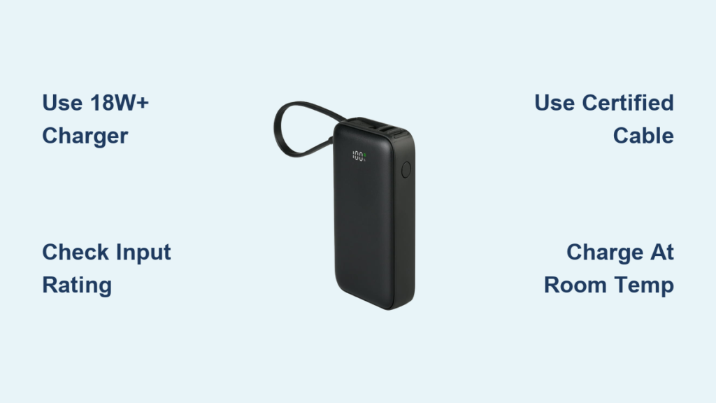
Your cable matters as much as your charger. Longer or thinner cables increase resistance, causing voltage drop. High-power charging at 100W or more requires thick, short cables. USB 2.0 cables support up to 7.5W for basic charging. USB 3.0 cables support up to 60W for fast charging and data. USB-C with E-Marker supports up to 240W for USB-PD 3.1 and laptops.
A $2 cable may not support 65W even if labeled fast. Always use certified cables, especially for high-wattage charging.
Charger Health and Battery Longevity
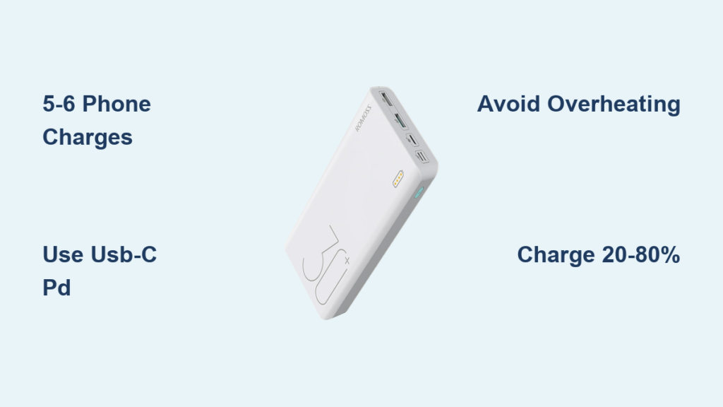
How you charge affects how long your battery lasts. Heat is the enemy of battery health. Fast charging generates heat, and prolonged high temperatures accelerate electrolyte breakdown, lithium plating, and capacity loss. Best practices include charging between 20% and 80% daily. Avoid overnight fast charging. Remove the phone case if it overheats. Use OEM or certified accessories. Partial cycles stress the battery less than full 0 to 100% charges.
Frequently Asked Questions About How Chargers Work
Does higher voltage mean faster charging?
Yes, but only if the device supports it. Power equals Voltage times Current, so increasing either boosts speed. Modern devices and chargers negotiate the optimal level through communication protocols.
Will a 100W charger damage my phone?
No. Devices only draw what they can handle. A 100W charger will safely deliver 18W to a phone that supports 18W charging. The device controls the power intake, not the charger.
Is 120W charging safe?
Yes, for devices designed for it. Dual-cell batteries, liquid cooling, and advanced Battery Management Systems prevent overheating. Manufacturers test these systems extensively before deployment.
Which is better: 5V 1A or 5V 2A?
5V 2A delivers 10W compared to 5W from 5V 1A, which is twice the speed. However, your device must support the higher current draw for this to work.
Can I use any USB cable with my charger?
No. Not all cables support fast charging. Wire gauge, length, and certification all affect performance. Use certified cables, especially for high-wattage charging.
Does wireless charging damage the battery?
Not directly, but the heat buildup from inefficiency can accelerate long-term degradation. The 70 to 85% efficiency means more energy becomes heat compared to wired charging.
Key Takeaways for Understanding How Chargers Work

A charger is far more than a simple power plug. It is a sophisticated power electronics system that converts dangerous high-voltage AC to safe low-voltage DC, regulates output precisely using feedback loops, communicates with your device to optimize charging, and protects against overvoltage, overcurrent, overheating, and short circuits. The actual charging happens inside your device, managed by the Battery Management System, not in the wall adapter. From the first rectifier to the final trickle charge, every component plays a role in delivering power safely and efficiently. The next time you plug in, remember that you are engaging a high-speed dance of electrons, algorithms, and engineering precision.