Building a power bank with 18650 batteries is a smart way to create a high-capacity, customizable charging solution at a fraction of the cost of commercial alternatives. Whether you’re repurposing old laptop cells or assembling a rugged off-grid backup, this guide walks you through every critical step—using only verified components, real-world test data, and safety-tested methods. You’ll learn how to select genuine 18650 cells, wire them safely in parallel, integrate a reliable power bank module, and assemble a durable, functional unit that charges your devices reliably.
The 18650 lithium-ion cell remains the gold standard for DIY power banks due to its proven capacity, availability, and performance. When combined with the right protection circuit and enclosure, even a simple 4-cell pack can deliver over 12,000 mAh—enough to charge a smartphone multiple times. But success hinges on avoiding common mistakes: using fake-rated cells, poor wiring practices, or ignoring safety protocols. This guide cuts through the misinformation and delivers a step-by-step blueprint based on actual builds and user-tested results.
Choose Genuine 18650 Cells to Avoid Fake Capacity Claims
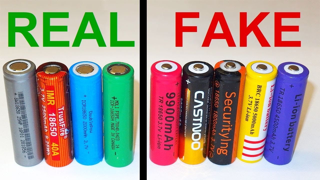
Stick to Verified High-Performance Models
Not all 18650s are equal—many budget cells claim 5,000 mAh or more, but these ratings are almost always fake. The highest legitimate capacity available today is 4,000 mAh, found in the Vapcell N40. For most builds, the Liitokala HG2 (3,000 mAh) offers the best balance of cost, reliability, and performance, priced around $1.75 per cell on AliExpress.
Trusted models include:
– Panasonic NCR18650B – 3,400 mAh, excellent cycle life
– Liitokala HG2 – 3,000 mAh, widely tested and dependable
– Vapcell N40 – 4,000 mAh, top-tier genuine capacity
– NCR 18650A – ~3,400 mAh, often salvaged from laptops
⚠️ Never use damaged, swollen, or punctured cells. They pose serious fire risks.
Test and Match Cells Before Assembly
Always verify voltage and internal resistance before connecting cells. Use a battery analyzer like the Liitokala M4 to:
– Confirm voltage (should be 3.6–3.8V for storage, up to 4.2V when charged)
– Measure actual capacity under load
– Check internal resistance—ideally below 100 mΩ
For multi-cell packs, only use cells within 0.03V of each other and with similar resistance. Mismatched cells can cause uneven discharge, overheating, or premature failure.
Salvaged cells from laptops or scooters may have higher resistance (~100 mΩ) and lower capacity (~2,000 mAh), making them suitable only for low-drain applications.
Select the Right Power Bank Module for Your Cell Count
Match the PCB to Your Configuration
The power bank module (PCB) manages charging, discharging, voltage conversion, and protection. Choosing the right one ensures safety and reliable performance.
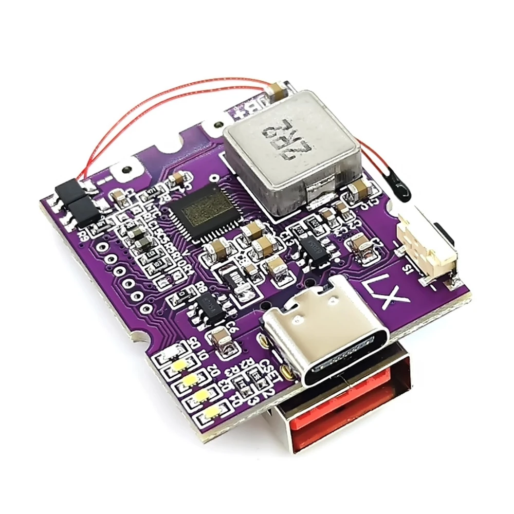
For 1–6 Cells: LX-LBU2C Module
- Best for beginners and small builds
- Supports 1S (single-cell voltage)
- Dual USB-A outputs (up to 2.4A total)
- Input via micro-USB or USB-C
- Built-in overcharge, over-discharge, and short-circuit protection
- Optional NTC thermistor input for temperature monitoring
- Costs under $5 on AliExpress
✅ Ideal for compact emergency chargers using salvaged or low-cost cells.
For 8-Cell Builds: A8 Module (Temu)
- Supports 1S8P (8 cells in parallel)
- Inputs: USB-C + micro-USB (5V/2A max)
- Outputs: 2 × USB-A (1A each, 3A combined)
- Includes protection circuit and LED indicator
- Comes with a snap-fit plastic case
- Priced at $13.32
✅ Great budget option for mid-size power banks with 24,000+ mAh capacity.
For 16–20 Cells: High-Cell-Count Module (AliExpress)
- Handles up to 1S20P (20 cells in parallel)
- Max output: 20W (5V/4A or 9V/2.2A)
- Charging input: ~10W, meaning 16–22 hours to fully charge
- Spring-loaded terminals for easy assembly
- Watch for loose connections—reinforce with glue if needed
✅ Best for large-capacity off-grid use, not fast charging.
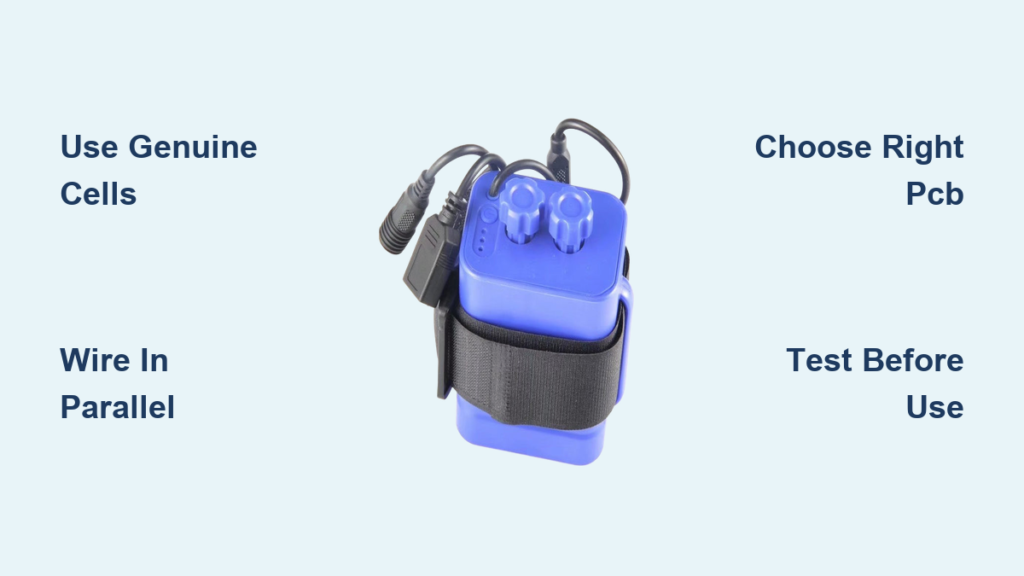
Wire Cells in Parallel for Safe, Stable Voltage Output
Why Use 1S Parallel Configuration?
For standard USB power banks, use a 1S (single series) configuration—all cells connected in parallel. This keeps voltage at 3.7V nominal (4.2V max), which the PCB boosts to 5V for USB devices.
In parallel wiring:
– All positives (+) are connected together
– All negatives (−) are connected together
– Voltage remains 3.7V
– Capacity adds up: 4 × 3,000 mAh = 12,000 mAh
🔋 No balancing required—parallel cells naturally equalize.
Avoid series configurations (2S, 3S) unless you need higher voltage. They require complex BMS balancing and buck converters, increasing risk and cost.
Connect Cells Safely: Spot Weld vs. Solder
Spot Welding (Recommended)
- Safest method
- Uses nickel strips to join cells
- Prevents heat damage to internal components
- Requires a spot welder (~$50–$100), but worth it for multiple builds
Soldering (Use with Caution)
If you must solder:
– Use flux and a 60W+ iron with a clean tip
– Limit contact to under 2 seconds per joint
– Clamp a metal heat sink (e.g., pliers) on the cell body
– Solder only to tabs or leads, never directly to flat ends
❌ Poor soldering can melt the internal seal, leading to leaks or fire.
Assemble the Battery Pack with Stability and Safety

Secure Cells in a Robust Enclosure
Choose an enclosure based on your build size:
– 3D-printed PLA cases: Customizable, lightweight, include alignment guides
– Snap-fit plastic cases (e.g., from Temu): Affordable, include rubber gaskets
– Metal project boxes: Sturdy but require full insulation to avoid shorts
Use hot glue to secure each layer of cells and prevent movement. Add insulating tape on top of all cells to avoid accidental contact with wires or metal parts.
Route Wires for Reliability
Use 14–16 AWG silicone wire for low resistance and flexibility. Keep wires:
– As short as possible
– Away from sharp edges
– Bundled with cable ties or adhesive clips
Solder or crimp the battery pack leads to the PCB’s B+ and B− terminals. Double-check polarity: red = positive (B+), black = negative (B−).
Install and Test the Power Bank Module
Connect PCB and Verify Functionality
Once cells are wired:
1. Connect B+ (battery positive) to PCB
2. Connect B− (battery negative) to PCB
3. Plug in NTC thermistor if using (optional for indoor use)
4. Close the case carefully, ensuring no wires are pinched
Power on the module and check:
– LED indicator lights up
– USB ports deliver ~5.1V (test with multimeter)
– No overheating or burning smell
Test Charging and Discharging
- Plug in a 5V/2A charger via micro-USB or USB-C
- Verify the PCB begins charging (LEDs usually blink or change color)
- After 10 minutes, check cell temperature—should not be hot
- Disconnect and test output with a phone or USB load
✅ If the device charges normally, your build is functional.
Add Safety and Utility Features
Prevent Over-Discharge
Most PCBs cut off at 3.0V, which is safe. For longer cell life, recharge before voltage drops below 2.9V. Never let cells sit below 2.5V—this causes permanent damage.
Use a low-voltage alarm module for early warning.
Install a Red LED Flashlight (Optional)
A built-in red flashlight preserves night vision. To build one:
– Wire 7 × 3mm red LEDs in parallel
– Each draws ~12.5mA → total ~88mA
– Use two 68Ω resistors in parallel (equals 34Ω) to limit current
– Connect to 5V USB line via a rocker switch
💡 Mount switch in a 10×15mm cutout. Flashlight runs independently.
Understand Risks and Travel Restrictions
Fire and Short-Circuit Hazards
Lithium-ion cells store significant energy. Risks include:
– Short circuits from loose wires
– Overheating during charging
– Mechanical damage (e.g., dropping)
Reduce risk by:
– Using protected circuits
– Avoiding spring-terminal-only holders
– Never leaving unattended during first charge
🔥 One user repaired a snapped cell holder with epoxy—reinforce weak points.
Air Travel Rules
Lithium-ion batteries are limited to 100 Wh (watt-hours) without approval.
For 18650s:
– 3.7V × 60Ah = 222 Wh → prohibited
– Max allowed: ~27,000 mAh at 3.7V
✈️ Always check FAA and IATA rules before flying.
Optimize Cost vs. Performance
| Option | Cost | Capacity | Safety |
|---|---|---|---|
| DIY 20-cell (HG2) | ~$50 | 60,000 mAh | Medium |
| Pre-made 20,000 mAh | ~$30 | 20,000 mAh | High |
| Salvaged-cell build | ~$15 | 30,000 mAh | Low–Medium |
DIY makes sense for custom high-capacity needs, education, or free salvaged cells.
Final Assembly and Maintenance Tips
- Seal snap-fit cases with epoxy or hot glue
- Reinforce broken tabs
- Recharge every 3–6 months if stored
- Keep in cool, dry place
- Clean contacts with isopropyl alcohol
With the right cells, proper wiring, and a matched PCB, your DIY 18650 power bank can be a reliable, long-lasting tool. Follow these steps, prioritize safety, and build with confidence.