Installing a battery power inverter gives you the freedom to run household appliances anywhere, whether in an RV, boat, or off-grid cabin. A battery power inverter wiring diagram serves as your roadmap for connecting the system safely and efficiently. Without proper wiring, you risk equipment damage, power loss, or even fire. This guide walks you through everything from understanding how inverters work to completing a safe, code-compliant installation.
By the end, you’ll understand how to read a wiring diagram, choose the right components, and integrate your inverter into your power system with confidence.
What Is a Battery Power Inverter and How Does It Work
A battery power inverter transforms stored DC electricity from batteries into usable AC power. Most household devices require 120V or 240V AC, but batteries supply low-voltage DC, typically 12V, 24V, or 48V. The inverter bridges this gap by converting battery power into household electricity.
The inverter doesn’t generate power. Instead, it draws energy from a battery bank charged by solar panels, shore power, generators, or alternators. Once powered, it delivers AC electricity through outlets, letting you run microwaves, laptops, refrigerators, and more, even off-grid.
The DC-to-AC Conversion Process
Inside the inverter, semiconductor switches called MOSFETs or IGBTs rapidly turn on and off in an H-bridge configuration. This creates a pulsating signal that Pulse Width Modulation shapes into a simulated AC waveform. The raw output is rough and full of electrical noise.
A filter circuit made of inductors and capacitors smooths the pulsating signal into a clean sine wave. Finally, the regulated AC power exits through outlets at standard voltage and frequency, ready to power your devices.
Why Inverter Efficiency Matters
Most inverters operate at 85 to 95 percent efficiency. For every 1000 watts used, 50 to 150 watts is lost as heat. High-quality wiring and proper setup reduce these losses significantly. Choosing the right cable gauge and keeping cables short directly impacts how much power reaches your appliances.
Pure Sine Wave vs Modified Sine Wave Inverters: Key Differences
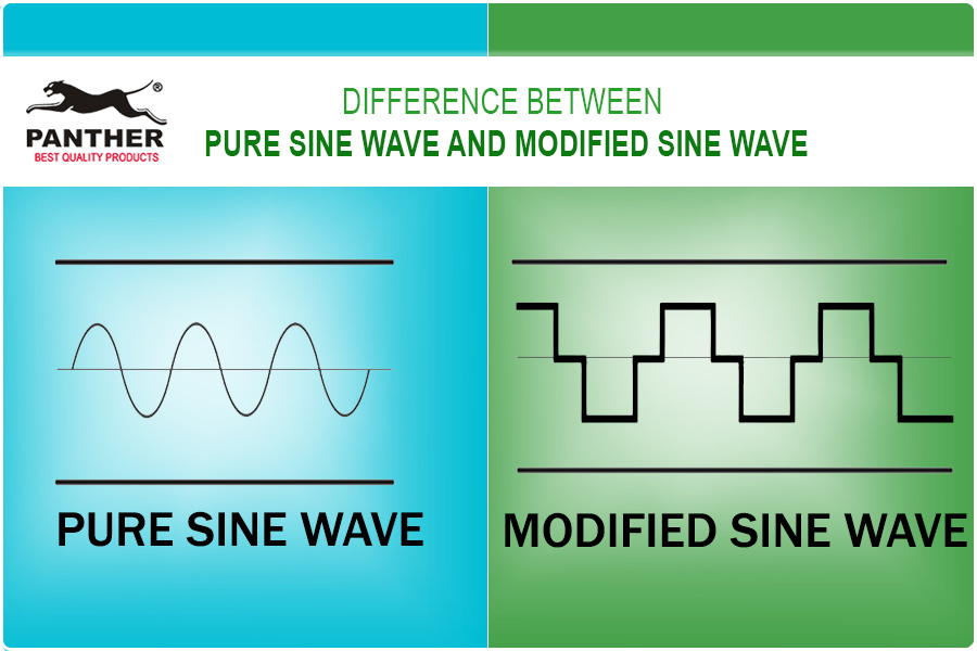
The type of AC waveform your inverter produces determines what devices it can safely power. Understanding the difference helps you choose the right equipment for your needs.
Pure Sine Wave Inverters
Pure sine wave inverters deliver smooth, grid-quality power identical to utility electricity. They’re ideal for sensitive electronics including laptops, TVs, medical devices, variable-speed motors, and audio systems.
Advantages include clean power with low harmonic distortion, quieter operation for compressors and fans, and higher efficiency with inductive loads. Two subtypes exist: low-frequency inverters use heavy transformers and handle surges well but are bulky, while high-frequency inverters are lightweight and more efficient, perfect for RVs and mobile setups.
Modified Sine Wave Inverters
Modified sine wave inverters produce a stepped, square-like waveform. They’re cheaper but less compatible with modern devices.
These inverters work best for incandescent lights, simple tools, and resistive heaters. Avoid using them with devices that hum, overheat, or malfunction under poor power quality, or anything with a microprocessor or digital display.
Pro Tip: If you plan to run modern electronics or use your system long-term, invest in a pure sine wave inverter. The extra cost saves money on damaged equipment.
How to Size Your Inverter for Your Power Needs

Choosing the wrong size leads to tripped breakers or dead batteries. Size your inverter based on both continuous and surge power requirements to ensure reliable operation.
Understanding Continuous vs Surge Power Ratings
Continuous wattage represents the maximum power the inverter can supply non-stop. Surge wattage indicates short-term peak capacity, usually two to three times the continuous rating, needed to start motor-driven devices like refrigerators and air conditioners.
Calculating Your Load Requirements
Start by listing all devices you plan to run simultaneously. Check labels or manuals for watts, or calculate using the formula watts equals volts times amps. Add up the running watts for all devices, then identify the highest surge requirement from any single device.
For example, a refrigerator requiring 600 watts running and 1800 watts surge, a microwave at 1000 watts running and 1200 watts surge, and a laptop at 100 watts running gives a total running load of 1700 watts with a highest surge of 1800 watts. Your total surge demand equals 1700 plus 1800, or 3500 watts.
Always add a 20 percent safety margin. This means multiplying your continuous rating by 1.2 for a minimum of 2040 watts and your surge rating by 1.2 for at least 4200 watts. Choose an inverter rated at least 2000 watts continuous and 4500 watts surge.
Common Inverter Sizes and Their Uses
Small inverters in the 300 to 600 watt range handle phones, lights, and fans. Medium units from 700 to 1000 watts power TVs, coffee makers, and laptops. Large inverters from 1000 to 2000 watts run fridges, microwaves, and AC units. Extra-large units from 2000 to 3000 watts handle multiple appliances, while high-capacity inverters above 3000 watts support full RV systems and power tools.
Warning: A 1000-watt 120-volt inverter cannot run a 240-volt appliance like an electric water heater. Always check voltage compatibility before purchasing.
Battery Power Inverter Wiring Diagram Integration Methods
How you connect your inverter depends on your specific needs. Three main approaches exist, each with different complexity levels and capabilities.
Plug-In Method for Occasional Use
The simplest approach uses the inverter’s built-in AC outlet with an extension cord. No permanent wiring is needed, making it ideal for occasional use or temporary setups. This method doesn’t power hardwired circuits in your RV or cabin.
Dedicated Outlets for Semi-Integration
Hardwire one or more AC outlets directly to the inverter. These outlets only live when the inverter is on, letting you power specific devices like kitchen counter outlets. This provides a simple upgrade path from plug-in use without full system integration.
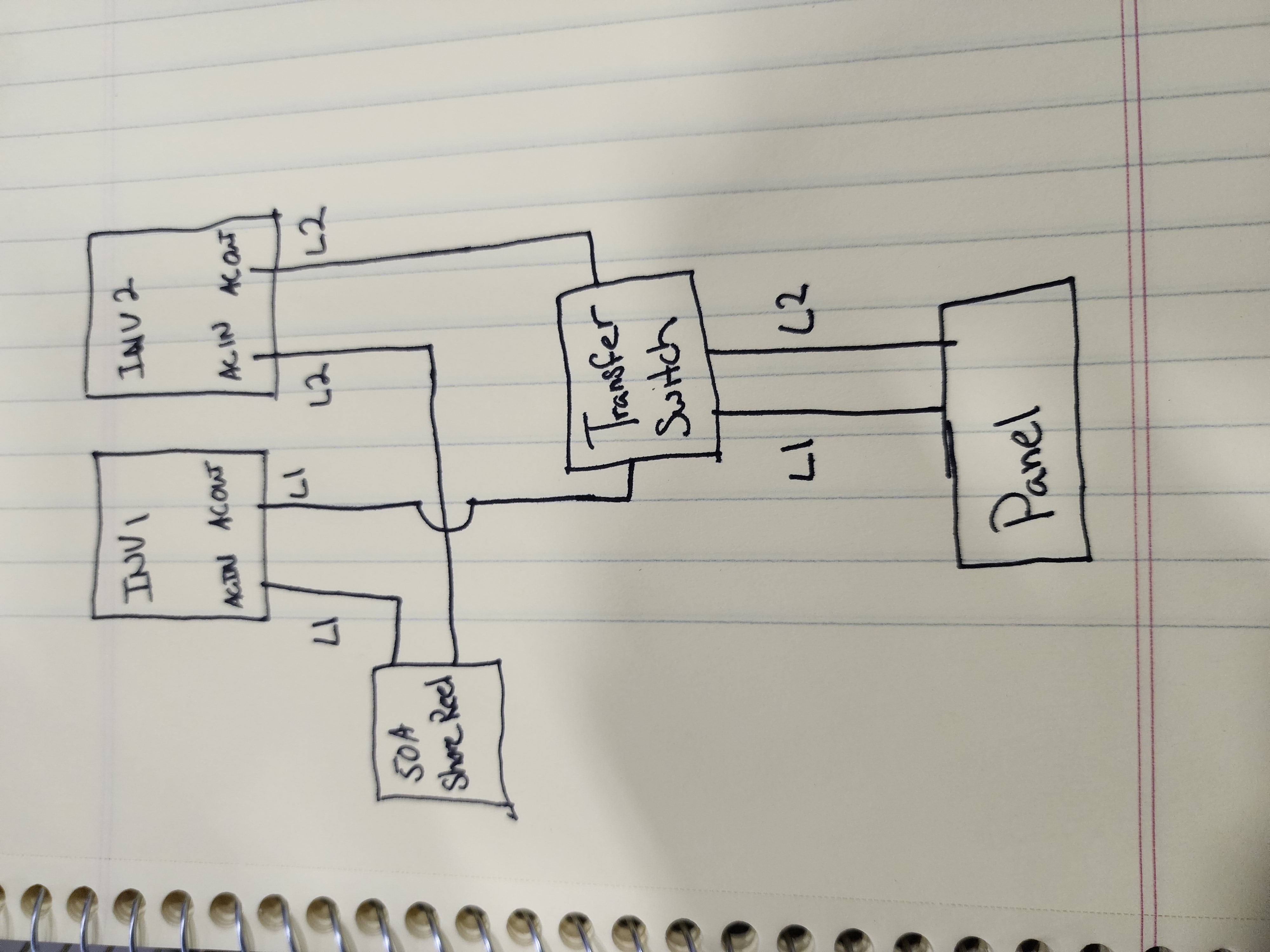
Full Integration with Transfer Switch
This professional-grade method requires a transfer switch to prevent backfeeding. Without one, plugging into shore power while the inverter is active sends AC backward into the inverter, destroying it.
A transfer switch prevents this by automatically or manually switching between shore power and inverter power, isolating the inverter when external power is present. Manual switches require you to flip a choice, while automatic transfer switches detect shore power and switch seamlessly.
The best option combines an inverter charger, which includes the inverter, battery charger, and automatic transfer switch in one unit. When shore power connects, it powers your AC loads and charges the battery bank. When disconnected, it automatically switches to inverter mode, eliminating the need for separate equipment.
Step-by-Step Inverter Installation Process
Follow these steps to install your inverter safely and correctly. Each phase matters for safety and performance.
Choosing the Mounting Location
Place the inverter within 3 to 6 feet of the battery bank to minimize DC cable length and voltage drop. Ensure at least 6 inches of clearance on all sides for cooling. Avoid damp, hot, or flammable areas, and don’t mount near lead-acid batteries unless the space is well-ventilated due to hydrogen gas risk.
Disconnecting All Power Sources
Before working, turn off shore power, flip the battery disconnect switch, and unplug the solar charge controller. This prevents accidental energizing during installation and protects both you and your equipment.
Securing the Inverter
Use the included mounting brackets and follow manufacturer spacing guidelines. Add anti-vibration pads if installing in a vehicle to reduce wear and noise from constant movement.
Grounding the Inverter
Locate the grounding lug, usually a green screw terminal. Connect a green or bare copper wire from it to the RV chassis frame or grounding busbar. Proper grounding ensures safety and reduces electrical noise throughout the system.
Connecting DC Cables to the Battery
Use thick, short cables to reduce voltage drop. For a 12-volt system at distances up to 3 feet, use 2 AWG for 100 amps, 1/0 AWG for 150 amps, and 3/0 AWG for 200 amps. At 6 feet, upgrade to 1/0 AWG for 100 amps, 3/0 AWG for 150 amps, and 4/0 AWG for 200 amps.
Install an inline fuse or breaker within 18 inches of the battery positive terminal. For a 2000-watt inverter on a 12-volt system, peak current equals roughly 167 amps, so use a 200-amp fuse. Connect the red positive cable from battery to inverter positive terminal and black negative cable from battery to inverter negative terminal. Double-check polarity, because reverse connections destroy inverters instantly.
Connecting AC Output
For plug-in use, simply plug an extension cord into the inverter outlet. For dedicated outlets, run NM or UF cable from inverter to new outlets and label them inverter only. For hardwire to breaker panel, connect inverter AC output to a dedicated double-pole breaker that complies with NEC Article 702 for emergency power systems. Use conduit for protection.
Critical: Never connect inverter output to the main service panel without a transfer switch. This causes backfeed and equipment damage.
Testing the System
Reconnect the battery, positive first, then turn on the inverter. Use a multimeter to check AC output, which should read approximately 120 volts. Plug in a lamp to verify operation, then gradually add load. If nothing works, check fuses, verify battery voltage exceeds 12.2 volts, and inspect all connections.
Understanding Inverter Wiring Diagrams and Symbols
A wiring diagram shows how all components connect. Learning the symbols helps you install confidently and troubleshoot effectively.
Common Symbols and Their Meanings
Plus and minus symbols indicate DC terminals. A tilde or AC label marks alternating current output. Three horizontal lines represent earth ground. A rectangle with a tilde shows the inverter block. A switch symbol indicates manual or automatic switching, and the battery symbol uses a long line for positive and short line for negative.
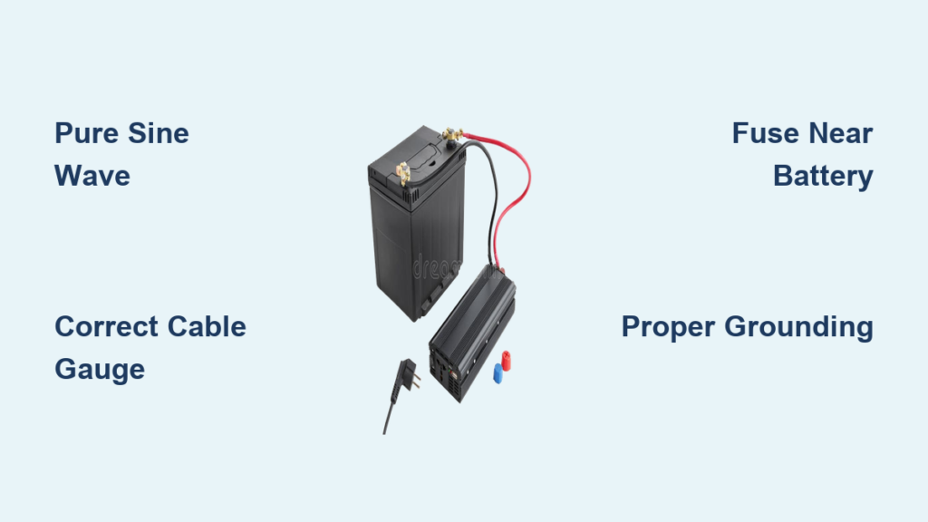
Key Circuit Paths in Your Diagram
The battery to inverter path uses thick red and black cables with a fuse near the battery. The grounding path runs a green wire from inverter to chassis. The AC output path wires from inverter to transfer switch or breaker. Control wires handle remote on/off and status monitoring, while shore power connects to the transfer switch, separated from inverter output.
Pro Tip: Always refer to your manufacturer’s wiring diagram. Model-specific details matter, and generic diagrams may not reflect your exact setup.
Essential Safety Precautions for Inverter Installation
Electrical work demands respect and caution. Following safety practices protects you and your equipment.
Electrical Safety Basics
Always work with power off. Use insulated tools and wear rubber-soled shoes. Install fuses on DC lines close to the battery, because they’re your first line of defense against shorts and overloads.
Thermal Management Requirements
Keep ambient temperature below 113 degrees Fahrenheit. Don’t cover the inverter during operation, and clean dust monthly to maintain airflow and prevent overheating.
Battery Selection Guidelines
Use deep-cycle batteries designed for repeated discharge, including AGM, gel, or lithium iron phosphate varieties. Lithium batteries offer the best weight, efficiency, and lifespan. Avoid car starter batteries, because they can’t handle deep discharges and fail quickly in inverter applications.
Daily Usage Best Practices
Turn off the inverter when not in use. Idle draw ranges from 0.5 to 2 amps, slowly draining your battery. Run DC devices directly when possible to save 10 to 15 percent energy that would otherwise be lost in conversion. Inspect connections quarterly for corrosion or looseness.
Troubleshooting Common Inverter Problems
When issues arise, systematic troubleshooting identifies the cause quickly.
Inverter Won’t Turn On
Dead batteries, blown fuses, or loose connections prevent startup. Check battery voltage, which should exceed 12.0 volts. Inspect the fuse near the battery and tighten all terminals.
Inverter Shuts Down Under Load
Low battery voltage causes this problem. Recharge the battery and check for excessive load or an undersized battery bank that can’t deliver enough power.
Overheating Issues
Poor ventilation or high ambient temperatures cause overheating. Improve airflow around the inverter or relocate it to a cooler location.
Appliance Not Working Properly
Modified sine wave inverters cause problems with sensitive electronics. Upgrade to a pure sine wave inverter for reliable operation with modern devices.
Humming Noise
Poor grounding or modified sine wave output creates humming. Secure the ground connection or switch to a pure sine wave inverter for quieter operation.
Maintenance Schedule for Your Inverter System
Regular maintenance keeps your system running reliably for years.
Monthly Tasks
Check all connections for tightness and corrosion. Clean dust from the inverter and surrounding area. Test battery voltage to ensure proper charge levels.
Quarterly Duties
Tighten all terminals securely. Inspect fuses for damage or corrosion. Verify grounding connections remain secure and effective.
Annual Requirements
Load test the inverter to ensure it handles rated capacity. Test the transfer switch operation if equipped. Check all wiring insulation for wear or damage.
Frequently Asked Questions About Battery Power Inverter Wiring Diagrams
Does an RV have both an inverter and a converter?
Yes. Most RVs come with a converter that charges batteries from AC power. An inverter, which converts DC to AC, is often added later. Many modern systems use inverter chargers that perform both functions in one unit.
What can run on an inverter in a camper?
AC devices like microwaves, TVs, coffee makers, air conditioners, and refrigerators (if AC-powered) run off the inverter. Any device plugged into inverter-powered outlets operates normally.
Should the inverter be on when plugged into shore power?
Only if using an inverter charger with pass-through capability. Otherwise, turn the inverter off when shore power is connected. The inverter isn’t needed and wastes energy.
Can I leave the inverter on all the time?
Not recommended. Inverters consume phantom power even when idle, draining your battery slowly. Turn it off when not in use to preserve battery life.
Can I wire multiple batteries to one inverter?
Yes. Wire batteries in series for higher voltage, parallel for more capacity, or series-parallel for both. Ensure all batteries are the same type, age, and capacity for balanced performance.
Key Takeaways for Installing Your Battery Power Inverter
A battery power inverter wiring diagram is your blueprint for safe, efficient off-grid power. Select a pure sine wave inverter for modern electronics, and size it with 20 percent headroom above your calculated load. Install a transfer switch or inverter charger to prevent dangerous backfeed when connecting to shore power. Use appropriate cable gauges, install fuses near the battery, and ground everything properly. Turn off the inverter when idle, and perform monthly inspections to catch problems early. When in doubt, consult a certified electrician, because incorrect wiring causes fire, equipment failure, or serious injury.