Your RV’s power inverter is the unsung hero of off-grid adventures, converting 12V DC battery power into usable 120V AC electricity so you can run your coffee maker, TV, or laptop without shore power. But when the outlets go dead or the inverter won’t turn on, it’s easy to assume the worst. In reality, most RV power inverter troubleshooting starts not with a failed unit, but with simple oversights like blown fuses, low battery voltage, or misidentified system failures.
Before replacing expensive components, follow this methodical guide to isolate the real problem. Whether you’re boondocking in the desert or prepping for a weekend getaway, understanding what’s actually wrong saves time, money, and frustration. You’ll learn how to test input voltage, interpret error lights, avoid overload traps, and distinguish true inverter faults from converter or battery issues that mimic failure.
Verify Inverter Power Status
Check Inverter On/Off State
The first step in RV power inverter troubleshooting is confirming the inverter is actually turned on. Many units have a physical switch on the device or a remote control panel mounted inside the RV. Ensure the switch is in the On position.
Some inverters auto-shut down due to low voltage, overheating, or overload. If the unit appears unresponsive:
• Turn it off completely
• Wait 30 seconds to reset internal circuitry
• Power it back on
If status lights still do not illuminate, proceed to voltage testing.
Interpret Status Lights and Error Codes
Most modern inverters use LED indicators to signal operating status or faults:
• No lights: Likely no DC input, blown fuse, or internal failure
• Flashing red light: Commonly indicates overload, low battery, or overheating
• Green light, no output: May mean AC circuits are off due to safety cutoffs or transfer switch issues
Always consult your inverter’s owner manual for model-specific error code meanings. A blinking pattern can pinpoint exact faults like short circuit or thermal shutdown.
Test DC Input Voltage
Measure Battery Voltage at Inverter
Use a digital multimeter set to DC volts. Place the red probe on the inverter’s positive input terminal and the black probe on the negative input terminal, then record the reading.
Expected values:
• 12.0 to 14.4V DC for 12V systems
• 24.0 to 28.8V DC for 24V systems
If voltage reads below 12.0V, the battery may be too discharged to power the inverter. A resting battery should read 12.7V at 100% charge, 12.4V at 75%, and 12.2V at 50%.
No Voltage? Trace the Circuit
If no DC voltage reaches the inverter:
• Check the battery disconnect switch to ensure it’s engaged
• Follow the red battery cable from the battery to the inline fuse or breaker
• Test continuity of ANL or MIDI fuses
• Inspect wiring for looseness, corrosion, or rodent damage
Install fuses within 18 inches of the battery to prevent fire hazards from short circuits.
Inspect Fuses and Circuit Protection
Locate and Test Key Fuses
Critical protection points include the inverter input fuse near the battery or inverter, the DC disconnect switch, and resettable circuit breakers in the DC line.
To test a fuse:
1. Remove the fuse visually or with multimeter in continuity mode
2. Look for broken filament or infinite resistance
3. Replace only with same amperage and type
A blown reverse-polarity fuse means the battery was connected backward, which often damages internal electronics and requires professional evaluation.
Evaluate Battery Health
Perform Resting Voltage Test
Disconnect all loads and charging sources. Wait 2 to 3 hours, then measure battery voltage:
• 12.7V equals fully charged
• 12.4V equals 75% capacity
• 12.2V equals 50% and requires immediate recharge
• Below 12.0V equals deeply discharged and may not recover
Repeated deep discharges shorten battery life significantly, especially in lead-acid types.
Load Test and Specific Gravity Check
For flooded lead-acid batteries, use a hydrometer to check electrolyte specific gravity. A reading of 1.265 indicates full charge, while below 1.225 indicates low charge. Perform a load test using a carbon pile tester or smart charger.
A weak battery cannot sustain inverter operation under load, even if voltage looks okay at rest.
Test AC Output from Inverter
Measure Voltage at Wall Outlets
Set your multimeter to AC volts. Insert probes into an inverter-powered outlet. The expected reading is 110 to 120V AC.
If no voltage exists:
• Confirm the inverter is powered on
• Test directly at the inverter’s AC output terminals
• Rule out tripped GFCI outlets, which can disable entire circuits
Verify Output with Known-Working Device
Plug in a simple device like a phone charger or LED lamp. If it works, the inverter is functional. If not, suspect internal failure or a wiring issue.
Pure sine wave inverters are required for sensitive electronics like TVs, laptops, and medical devices. Modified sine wave units may cause interference or improper operation.
Diagnose Overload Faults
Recognize Overload Symptoms
Common signs include the inverter beeping repeatedly, a red error light flashing, and automatic shutdown after a few seconds. The cause is total appliance load exceeding the inverter’s continuous or surge wattage.
A 700W microwave can draw 1200W at startup. A 1000W inverter may fail under this surge load.
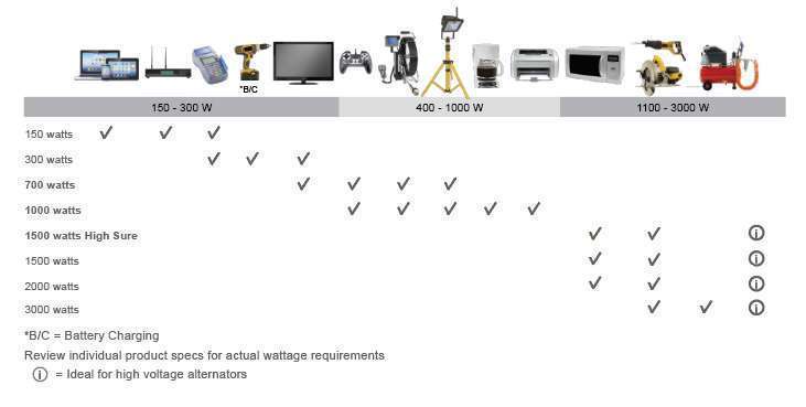
Match Loads to Inverter Capacity
| Inverter Size | Continuous | Surge | Example Loads |
|---|---|---|---|
| 300W | 300W | 600W | Phone, lights |
| 1000W | 1000W | 2000W | Laptop, coffee maker |
| 2000W | 2000W | 4000W | Microwave, fan |
| 3000W+ | 3000W+ | 6000W+ | Portable AC, kettle |
To prevent overloads, disconnect all devices, restart the inverter, then reconnect appliances one at a time. Avoid running high-draw devices simultaneously.
Address Overheating Issues
Identify High-Temperature Triggers
Symptoms include the inverter shutting down after 5 to 10 minutes, the fan running constantly or not at all, and hot casing or a burnt smell. Causes include blocked cooling vents, poor ventilation, prolonged heavy load, and ambient temperatures above 40°C.
Most inverters auto-shutdown at internal temperatures above 65°C to 70°C.
Inspect Cooling Fan and Vents
Listen for fan activation under load. Feel air discharge, which should be strong. Clean dust with compressed air. Ensure the inverter is not installed in an enclosed, unventilated compartment.
Improve installation by placing the inverter in a shaded, well-ventilated area. Add a thermostatically controlled auxiliary fan in hot climates. Schedule quarterly cleaning of the fan and heat sink.
Isolate Short-Circuit Faults
Unplug All Devices
A short circuit can occur in a faulty appliance, damaged extension cord, moisture in an outlet, or internal inverter components.
Steps to diagnose:
1. Unplug everything from inverter-powered outlets
2. Turn off and disconnect DC input
3. Inspect wiring for fraying, charring, or corrosion
Test for Continuity
Set your multimeter to continuity mode. Test between hot and neutral at the AC output. Any beep indicates a short. Repeat between hot and ground.
If continuity is detected with no load connected, internal PCB or MOSFET damage is likely and the unit requires service.
Detect Internal Hardware Failure
Identify Signs of Damage
Symptoms of internal failure include no display or power despite good input, a burning smell or visible charring, intermittent operation, and unusual buzzing or clicking.
Common causes include lightning strike or voltage spike, reverse polarity during installation, prolonged overheating, and aging components.
Decide on Repair vs. Replacement
Do not attempt field repair unless certified. Replace the entire unit or send it to an authorized service center. Match replacement specs for voltage, output waveform, power rating, and mounting type.
Install surge protectors on both AC and DC sides to prevent future damage.
Rule Out Converter Problems
Understand Converter vs. Inverter
A converter changes 120V AC shore power to 12V DC to charge batteries and run 12V systems. A failing converter can mimic inverter issues. If 12V devices fail only when not on shore power, it’s likely a battery or inverter issue. If they fail on shore power, suspect the converter.
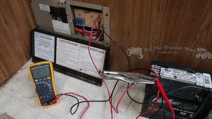
Test Converter Output
Measure DC voltage at the distribution panel while on shore power. Expected voltage is 13.6 to 14.4V DC. Below 13V indicates a problem with input AC voltage, fuses, cooling fan operation, or the inlet receptacle.
A user replaced a converter with no fix, only to find the shore power inlet was loose and not delivering 120V. Repairing the inlet restored function.
Follow System-Level Diagnostic Flow
Use the Decision Tree
Start with this sequence when nothing works:
-
Is anything working?
• Only 12V devices: Check inverter, battery, DC fuses
• Only 120V devices: Check battery charge, converter
• Nothing works: Check shore power, main breaker, GFCI -
Test shore power using an RV tester or EMS to verify polarity, grounding, and voltage. Reset GFCI outlets. Check pedestal voltage.
-
Test battery and inverter by confirming input voltage, testing AC output, and identifying if input is good but no output indicates inverter failure.
Prevent Future Failures
Upgrade to Smart Components
Replace old 2-stage converters with 3- or 4-stage smart chargers for better battery health. Install lithium batteries, which maintain stable voltage under load and improve inverter efficiency. Use remote monitoring systems to track voltage, current, and state of charge.
Maintain Regularly
• Visual inspection of vents and connections: Monthly
• Clean inverter fan and vents: Quarterly
• Check fuse and terminal tightness: Biannually
• Battery voltage check: Weekly for full-timers
• System load audit: Annually
Carry spare fuses and a portable DMM for roadside fixes.
Final Safety and Best Practices
Always Disconnect Before Working
Turn off and disconnect the battery before touching any DC wiring. Use insulated tools and wear safety glasses. Install disconnect switches for safe servicing.
Avoid common installation errors like using undersized cables, poor grounding, or mixing battery chemistries.
Most inverter failures stem from poor installation, missing fuses, bad grounding, or loose terminals. Successful RV power inverter troubleshooting is about testing in order, starting with power and moving to fuses, then battery, then verifying input and output.
Frequently Asked Questions About RV Power Inverter Troubleshooting
Why does my RV inverter turn on but produce no AC output?
Check if the inverter is properly connected to the battery and that the battery has sufficient voltage. Test the AC output with a multimeter set to AC volts. If voltage reads zero, the inverter may have internal failure or a tripped GFCI outlet may be disabling the circuit.
Can a weak battery cause inverter overload errors?
Yes. A weak or discharged battery cannot supply sufficient power under load, causing the inverter to shut down with overload symptoms. Test resting battery voltage, which should be at least 12.4V for the inverter to operate properly.
How do I know if my converter is failing instead of my inverter?
Test 12V devices while on shore power versus while off-grid. If 12V lights dim or devices fail only when connected to shore power, the converter is likely faulty. If they fail when disconnected from shore power, the inverter or battery is the problem.
What size inverter do I need for a microwave?
A 700W microwave draws approximately 1200W at startup. You need an inverter with at least 1500W continuous rating and 2000W or higher surge capacity to run a microwave reliably.
Why does my inverter beep continuously?
Continuous beeping typically indicates an overload condition or low battery voltage. Disconnect some appliances, check battery charge level, and ensure the total load does not exceed the inverter’s rated capacity.
Should I replace my modified sine wave inverter with a pure sine wave unit?
Yes, if you plan to run sensitive electronics like TVs, laptops, medical devices, or modern appliances. Pure sine wave inverters produce clean power similar to household grid electricity and prevent damage to sensitive equipment.
Key Takeaways for RV Power Inverter Troubleshooting
Successful RV power inverter troubleshooting requires a systematic approach. Start by verifying the inverter is turned on and check status lights for error codes. Test DC input voltage at the battery and inverter terminals to ensure proper power delivery. Inspect all fuses and circuit protection, including the battery disconnect switch and inline fuses near the battery.
Evaluate battery health through resting voltage tests and load testing. A weak or discharged battery will cause inverter failure even when the inverter itself is functioning correctly. Test AC output at wall outlets and verify with a known-working device.
Address overload faults by matching appliance loads to inverter capacity, and prevent overheating by ensuring proper ventilation and fan operation. Rule out converter problems by testing 12V systems on and off shore power. Finally, document all findings and perform regular maintenance to prevent future failures.